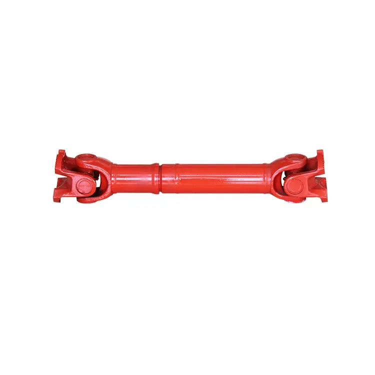
Descrição do produto
Product Details
A coupling is a mechanical component that is used to firmly connect the driving shaft and driven shaft in different mechanisms together, rotate together, and transmit motion and torque. It is also sometimes used to connect shafts and other parts (e.g. gears, pulleys, etc.). It usually consists of 2 parts, which are connected by a key or clamping fit, respectively, and fastened at the 2 shaft ends. Couplings can compensate for deviations (including axial, radial, angular or combined offset) between 2 shafts due to inaccurate manufacturing and installation, deformation or thermal expansion during operation, as well as shock and vibration absorption. The most commonly used couplings have been standardized or normalized. In general, it is only necessary to select the type of coupling correctly and determine the type and size of the coupling. If necessary, check and calculate the carrying capacity of the vulnerable and weak links; When the rotational speed is high, it is necessary to check the centrifugal force on the outer edge and the deformation of the elastic element for balance detection.
Couplings are used to connect shafts in different mechanisms, mainly by rotation, thus transferring torque. Under the action of high-speed power, the coupling has the function of buffering and damping, and the coupling has good service life and working efficiency.
The function of the coupling:
a device that connects 2 shafts or shafts with rotating parts and rotates together in the process of transmitting motion and power and does not break away under normal circumstances. Sometimes, it is also used as a safety device to prevent the connected parts from bearing excessive loads and play the role of overload protection. The coupling is installed between the active side and the passive side of the power transmission, which plays the role of transferring torque, compensating the installation deviation between shafts, absorbing equipment vibration and buffering load impact. One of the functions of couplings is to absorb and compensate for deviations between shafts through their own deformation. The greater the elasticity, the stronger the ability to absorb the deviation; The less flexibility you have, the less ability you have to absorb deviations. In general, the deviation between the shaft and the shaft can be divided into the following 3 aspects: The connection between the coupling and the peripheral equipment is achieved by inserting the shaft of the device into the shaft hole of the coupling.
1. The role of the coupling is to connect the 2 shafts in different mechanisms (drive shaft and driven shaft) to rotate and transmit torque together, and some couplings also have the role of buffering, damping and improving the dynamic performance of the shafting.
2. Eliminate the inertia of the radial force, connect the motor spindle with the load, and use a coupling to weaken the starting power when the motor starts.
3. Power conduction, transmission of power and torque (improve the performance of the transmission system)
4. Different degrees of vibration reduction and buffering
5. Disconnect when the load is too large to play a protective role
6. Good for maintenance
7. Change the drive direction
8. Concentricity correction (different degrees of axial, radial and angular compensation performance)
The types of couplings
Bellows coupling
The bellows coupling is composed of 2 hubs and thin-walled bellows that are welded or bonded together. The input end of the coupling structure is a clamping structure, and the pre-tightening force is generated by clamping screws, and the power input shaft is firmly connected with the clamping hoop. Flexible and rigid stainless steel bellows have the ability to correct radial, axial and angular deviations, transmit torque with zero backlash, and have different bushings designed to meet different equipment requirements.
A plum coupling
Plum coupling is a widely used coupling, elastomer is a balance accessory, can zero back backlash transfer torque and shock absorption. The different types of elastomers determine the characteristics of the entire drive system. Zero back backlash is achieved through a pre-pressure between the 2 coupling bushing and the elastomer. Its elastomer is usually composed of engineering plastics or rubber. Because elastomers have the function of buffering and reducing vibration, they are widely used in the case of strong vibration.
Safety coupling
The safety coupling mainly relies on the spring force and works with the shape, which can protect the adjacent drive components from damage caused by overload. Divided into synchronous type, stepping type 60°, failure protection type, closed. Features of a special butterfly spring system. No torque transfer is possible until the torque control nut is linked to the butterfly spring to apply pressure. The service life of the safety coupling is largely determined by the speed at which the coupling is disengaged and the holding time of the coupling. The safety coupling is not worn when it is engaged, does not require maintenance, and does not require additional refueling.
Rigid coupling
The rigid coupling is actually a torsional rigid coupling. Even under load, there is no turning clearance. Even if there is a deviation that creates a load, the rigid coupling is still rigid to transmit torque. Rigid couplings need to be used to connect 2 shafts in strict alignment without relative misalignment, so they are used less in motor test systems. Of course, if the relative displacement can be successfully controlled (the alignment accuracy is high enough), rigid coupling can also play an excellent role in the application. In particular, the small size rigid coupling has the advantages of light weight, ultra-low inertia and high sensitivity. In practical applications, rigid couplings have the advantages of maintenance-free, ultra-oil resistance and corrosion resistance.
Long shaft coupling
The standard length of the long-shaft coupling is up to 6 meters, and no intermediate support is required. The 2 ends are connected by high-performance stainless steel or high-strength aluminum, and the middle pipe is made of different materials such as steel, aluminum or carbon fiber. The allowable deviation range, speed and torque of the standard model should be reduced by 30%. The allowable working speed depends on the total length of the joint shaft and can also be adjusted according to demand.
Diaphragm coupling
Diaphragm couplings transfer torque by friction and diaphragm assembly, so there are no stress concentrations, backbacklash and micro-displacement that occur when torque is transferred through shoulder bolts. It has a near unlimited service life and increases the torsional rigidity of the individual components of the complete coupling, which can compensate for a variety of combined shaft assembly errors as a percentage of the total allowable error value listed in the data sheet. The sum of the percentages of the 3 errors cannot exceed 100%.
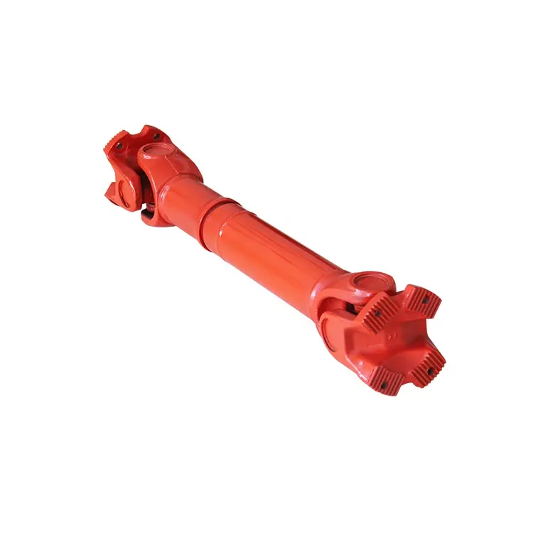
Descrição do produto
As a professional manufacturer for propeller shaft, we have +1000 items for all kinds of car, At present, our products are mainly sold in North America, Europe, Australia, South Korea, the Middle East and Southeast Asia and other regions, applicable models are European cars, American cars, Japanese and Korean cars, etc. /* January 22, 2571 19:08:37 */!function(){function s(e,r){var a,o={};try{e&&e.split(“,”).forEach(function(e,t){e&&(a=e.match(/(.*?):(.*)$/))&&1
| Padrão ou não padrão: | Padrão |
|---|---|
| Torque: | >80N.M |
| Diâmetro do furo: | According to Specific Drawings |
| Personalização: |
Disponível
| Solicitação personalizada |
|---|
.shipping-cost-tm .tm-status-off{background: none;padding:0;color: #1470cc}
|
Custo do frete:
Frete estimado por unidade. |
sobre o custo do frete e o prazo estimado de entrega. |
|---|
| Método de pagamento: |
|
|---|---|
|
Pagamento inicial Pagamento integral |
| Moeda: | US$ |
|---|
| Devoluções e reembolsos: | Você pode solicitar um reembolso em até 30 dias após o recebimento dos produtos. |
|---|
How do cardan shafts ensure efficient power transfer while maintaining balance?
Cardan shafts are designed to ensure efficient power transfer while maintaining balance between the driving and driven components. They employ various mechanisms and features that contribute to both aspects. Let’s explore how cardan shafts achieve efficient power transfer and balance:
1. Universal Joints:
– Cardan shafts utilize universal joints, also known as U-joints, to transmit torque from the driving component to the driven component. Universal joints consist of a cross-shaped yoke with needle bearings at each end. These needle bearings allow the joints to pivot and accommodate angular misalignment between the driving and driven components. By allowing for flexibility in movement, universal joints ensure efficient power transfer even when the components are not perfectly aligned, minimizing energy losses and maintaining balance.
2. Misalignment Compensation:
– Cardan shafts are designed to compensate for misalignment between the driving and driven components. The universal joints, along with slip yokes and telescopic sections, allow the shaft to adjust its length and accommodate variations in alignment. This misalignment compensation capability ensures that the cardan shaft can transmit power smoothly and efficiently, reducing stress on the components and maintaining balance during operation.
3. Balanced Design:
– Cardan shafts are engineered with a balanced design to minimize vibration and maintain smooth operation. The shaft tubes are typically symmetrically constructed, and the universal joints are positioned to distribute the mass evenly. This balanced design helps to reduce vibration and minimize the occurrence of unbalanced forces that can negatively impact power transfer and overall system performance. By maintaining balance, cardan shafts contribute to efficient power transmission and improve the lifespan of the components involved.
4. High-Quality Materials and Manufacturing:
– The materials used in the construction of cardan shafts, such as steel or aluminum alloy, are carefully selected for their strength, durability, and ability to maintain balance. High-quality materials ensure that the shafts can withstand the torque and operational stresses without deformation or failure, promoting efficient power transfer. Additionally, precise manufacturing processes and quality control measures are employed to ensure that the cardan shafts are accurately balanced during production, further enhancing their efficiency and balance.
5. Regular Maintenance and Inspection:
– To ensure continued efficient power transfer and balance, regular maintenance and inspection of cardan shafts are essential. This includes periodic lubrication of the universal joints, checking for wear or damage, and addressing any misalignment issues. Regular maintenance helps to preserve the balance of the shaft and ensures optimal performance and longevity.
Overall, cardan shafts ensure efficient power transfer while maintaining balance through the use of universal joints for torque transmission, misalignment compensation mechanisms, balanced design, high-quality materials, and regular maintenance. By incorporating these features, cardan shafts contribute to the smooth operation, reliability, and longevity of various applications in automotive, industrial, and other sectors that rely on efficient power transmission.
Quais precauções de segurança devem ser seguidas ao trabalhar com eixos cardan?
Trabalhar com eixos cardan exige o cumprimento de certas precauções de segurança para evitar acidentes, lesões e danos ao equipamento. Seja durante a instalação, manutenção ou reparo, é essencial seguir estas diretrizes de segurança:
1. Equipamento de Proteção Individual (EPI):
– Use sempre os equipamentos de proteção individual adequados, incluindo óculos de segurança, luvas e roupas de proteção. Os EPIs ajudam a proteger contra possíveis riscos, como detritos voadores, objetos cortantes ou contato com lubrificantes ou produtos químicos.
2. Treinamento e Familiaridade:
– Assegure-se de que o pessoal que trabalha com eixos cardan esteja devidamente treinado e familiarizado com os equipamentos e procedimentos envolvidos. Eles devem compreender os riscos potenciais, as práticas de operação seguras e os procedimentos de emergência.
3. Procedimentos de bloqueio/etiquetagem:
– Antes de trabalhar em eixos cardan, siga os procedimentos adequados de bloqueio/etiquetagem para isolar e desenergizar o equipamento. Isso evita a ativação ou movimentação acidental do eixo durante a execução de atividades de manutenção ou reparo.
4. Fixe o equipamento:
– Antes de iniciar qualquer trabalho no eixo cardan, certifique-se de que o equipamento ou veículo esteja firmemente apoiado e imobilizado. Isso evita movimentos ou rotações inesperadas do eixo, reduzindo o risco de emaranhamento ou ferimentos.
5. Ventilação:
– Ao trabalhar em espaços fechados ou áreas com pouca ventilação, assegure-se de que a ventilação seja adequada ou utilize equipamento de proteção respiratória apropriado para evitar a inalação de fumos, gases ou partículas de poeira nocivas.
6. Técnicas adequadas de levantamento de peso:
Ao manusear eixos cardan ou componentes pesados, utilize técnicas adequadas de elevação para evitar esforços ou lesões. Utilize equipamentos de elevação, como guindastes ou talhas, quando necessário, e certifique-se de não exceder a capacidade de carga.
7. Inspeção e Manutenção:
– Inspecione regularmente o estado do eixo cardan, incluindo juntas universais, garfos deslizantes e outros componentes. Procure sinais de desgaste, danos ou desalinhamento. Realize a manutenção e lubrificação de rotina conforme recomendado pelo fabricante para garantir uma operação segura e eficiente.
8. Evite exceder os limites de projeto:
– Opere o eixo cardan dentro dos limites de projeto especificados, incluindo capacidade de torque, velocidade e ângulos de desalinhamento. Exceder esses limites pode levar ao desgaste prematuro, falha mecânica e riscos à segurança.
9. Descarte adequado de peças e lubrificantes usados:
– Descarte peças usadas, lubrificantes e outros materiais residuais de acordo com as normas locais e as melhores práticas ambientais. Siga os procedimentos adequados de descarte para evitar a poluição e possíveis danos ao meio ambiente.
10. Resposta a emergências:
– Familiarize-se com os procedimentos de resposta a emergências, incluindo primeiros socorros, prevenção de incêndios e planos de evacuação. Mantenha acesso a informações de contato de emergência e aos equipamentos de segurança necessários, como extintores de incêndio, nas proximidades da área de trabalho.
É importante observar que as precauções de segurança acima servem como diretrizes gerais. Consulte sempre as diretrizes de segurança específicas fornecidas pelo fabricante do eixo cardan ou do equipamento para obter quaisquer precauções ou recomendações adicionais.
Seguindo essas precauções de segurança, os indivíduos que trabalham com eixos cardan podem minimizar os riscos associados à sua operação e garantir um ambiente de trabalho seguro.

Você pode explicar os componentes e a estrutura de um sistema de eixo cardã?
Um sistema de eixo cardã, também conhecido como eixo de transmissão ou eixo de acionamento, consiste em vários componentes que trabalham em conjunto para transmitir torque e potência rotacional entre componentes não alinhados. A estrutura de um sistema de eixo cardã normalmente inclui os seguintes componentes:
1. Tubos do eixo:
Os tubos do eixo são os principais elementos estruturais de um sistema de eixo cardã. São tubos cilíndricos fabricados com materiais duráveis e de alta resistência, como aço ou liga de alumínio. Os tubos do eixo constituem a espinha dorsal do sistema e são responsáveis pela transmissão de torque e potência rotacional. São projetados para suportar cargas elevadas e forças de torção sem deformação ou falha.
2. Juntas universais:
As juntas universais, também conhecidas como juntas U ou juntas cardan, são componentes cruciais de um sistema de eixo cardan. Elas são usadas para conectar e articular os tubos do eixo, permitindo o desalinhamento angular entre os componentes motor e motorizado. As juntas universais consistem em um garfo em forma de cruz com rolamentos de agulha em cada extremidade. O garfo conecta os tubos do eixo, enquanto os rolamentos de agulha permitem o movimento rotacional e a flexibilidade necessários para a compensação do desalinhamento. As juntas universais permitem que o sistema de eixo cardan transmita torque mesmo quando os componentes motor e motorizado não estão perfeitamente alinhados.
3. Jugos deslizantes:
– Os garfos deslizantes são componentes usados em sistemas de eixo cardan que permitem o ajuste de desalinhamento axial. Normalmente, estão localizados em uma ou ambas as extremidades dos tubos do eixo e proporcionam uma conexão deslizante entre o eixo e o componente motor ou acionado. Os garfos deslizantes permitem que o eixo ajuste seu comprimento e compense as variações na distância entre os componentes. Essa característica é particularmente útil em aplicações onde a distância entre os componentes motor e acionado pode variar, como em veículos com distância entre eixos ajustável ou máquinas com pontos de fixação variáveis.
4. Flanges e garfos:
– Flanges e garfos são usados para conectar o sistema de eixo cardã aos componentes de acionamento e acionados. Os flanges são normalmente parafusados ou soldados às extremidades dos tubos do eixo e fornecem um ponto de conexão seguro. Eles possuem uma face flangeada com furos para parafusos que se alinham com o flange correspondente no componente de acionamento ou acionado. Os garfos, por outro lado, são componentes em forma de cruz que conectam as juntas universais aos flanges. Eles possuem furos ou ranhuras que acomodam os rolamentos de agulha das juntas universais, permitindo o movimento rotacional e a transferência de torque.
5. Equilíbrio de pesos:
Os contrapesos são utilizados para equilibrar o sistema de eixo cardã e minimizar vibrações. À medida que o eixo gira, desequilíbrios na distribuição de massa podem causar vibrações, ruídos e redução do desempenho. Os contrapesos são estrategicamente posicionados ao longo dos tubos do eixo para contrabalançar esses desequilíbrios. Eles redistribuem a massa, garantindo que os componentes rotativos do sistema de eixo cardã estejam devidamente balanceados. O balanceamento adequado melhora a estabilidade, reduz o desgaste dos rolamentos e de outros componentes e aumenta o desempenho geral e a vida útil do sistema de eixo.
6. Recursos de segurança:
– Alguns sistemas de eixo cardan incorporam recursos de segurança para proteção contra falhas mecânicas. Por exemplo, proteções ou blindagens podem ser instaladas para evitar o contato com componentes rotativos, reduzindo o risco de acidentes ou lesões. Em aplicações onde podem ocorrer forças ou torques excessivos, os sistemas de eixo cardan podem incluir mecanismos de segurança como pinos de cisalhamento ou limitadores de torque. Esses recursos são projetados para proteger o eixo e outros componentes contra danos por cisalhamento ou desengate em caso de sobrecarga ou torque excessivo.
Em resumo, um sistema de eixo cardan consiste em tubos de eixo, juntas universais, garfos deslizantes, flanges e garfos, além de contrapesos e dispositivos de segurança. Esses componentes trabalham em conjunto para transmitir torque e potência rotacional entre componentes desalinhados, permitindo a compensação de desalinhamentos angulares e axiais. A estrutura e os componentes de um sistema de eixo cardan são cuidadosamente projetados para garantir transmissão de potência eficiente, flexibilidade, durabilidade e segurança em diversas aplicações.


editor by CX 2024-05-13


