Product Description
Custom manufacturing CNC machining aluminum/stainless steel/steel alloy/brass tractors/agricultural machinery tail shaft/Propeller shaft/Cardan shaft/Driveshafts
Click here and specify your inquiry, contact us to get an online quote now!
How to get a quote?
1. First: Email us and offer your 3D drawing/2D drawing to us to quote.
2. Second: Let us know the required material, surface finish and special tolerance requirements, quantity information, we’ll arrange for our engineer to review your drawings and quote soon!
Note: Workable 3D Drawing Formats: STEP/IGS/X_T/STL/SOLIDWORKS etc, 2D Drawing with PDF will do.
Project Support: Free Sample Offered Before Production starts
Examples projects
What we can offer
| Advantages | »Free sample offered before production »Good machining quality and warm service »Reasonable Pricing and outstanding quality provided »Competitive shipping cost service with discount sometimes »MOQ 1PCS and small quantity order accepted, mass production supported »Professional engineering service when any modification required »Any turnkey assembly or customized package requirements, we’ll meet your demands! |
|||||
| Equipment |
»20 sets of CNC turning machines; »30 sets of the most technologically advanced machining CNC milling machines; »25 sets of Multi-Spindle Japan Precision Swiss CNC lathes |
|||||
| RFQ | Customer Inquiry →Engineering Communication →Cost Analysis →Sales Analysis →Quote to Customer » 1-3 Work Days Only » Submit RFQ with complete commercial terms |
|||||
| Sample Making | Sample Order → Engineering Review → Sample Plan to Customer → Sample Status Tracking → Submit Samples with Doc. » Sample L/T: 1 week » Continuous Sample Status Tracking » Complete Documents for sample approval |
|||||
| Order Management | CRM System → Open Order Confirm → Logistic Arrangement. » Production L/T: 2-4 wks » Weekly Open Order Confirm » Preferred 3PL Service to Customers |
|||||
| Quality Control | Certificates: RoHS, ISO9001:2008, SGS. IQC → IPQC → OQC/FQC → Quality Complain Feedback → Audit & Training. » Plant Audit and Qualified by world famous company » Strict Quality Management Procedure with Traceability |
|||||
| Application | »Aerospace »Automotive »Lighting fittings »Motorbike »PhotoGear »EDC Tools » Marine »Office equipment »Home appliance »Medical equipment »Telecommunication »Electrical & Electronics »Fire detection system, etc. |
|||||
Production information
1). Material Capabilities: Following GB, DIN, and ISO and applying good quality homemade and import materials, we have already provided single/assembly products for international customers mainly from the USA and Europe, etc.
| Stainless Steel | SS201, SS301, SS303, SS304, SS316, SS416 etc. |
| Steel | Mild steel, Carbon steel, 4140, 4340, Q235, Q345B, 20#, 45#, etc. |
| Brass | HPb63, HPb62, HPb61, HPb59, H59, H62, H68, H80 etc. |
| Copper | C11000, C12000, C12000 C36000 etc. |
| Aluminum | AL6061, Al6063, AL6082, AL7075, AL5052, A380 etc. |
| Iron | A36, 45#, 1213, 12L14, 1215 etc. |
| Plastic | ABS, PC, PE, POM, Delrin, Nylon, PP, PEI, Peek etc. |
2). Quality control:
*We have specialized QC testers to check the quality of the products according to different customers’ requirements. Usually, it’s a random inspection, and we also offer 100% inspection at a reasonable price if required.
*We have IQC to check the dimensions and surface of the incoming material
*We have PQC to inspect full-course during the manufacturing processing
*We have FQC to inspect all the anodizing/plating and other finishes’ products from our supplier and proceed with the professional quality and appearance inspection before shipping.
3).Surface Finish: sandblasted/normal and hard anodized finish/polish/coating/polish/passivation/plating/brush/heat treatment/fine glass beads/grounding/tumbled finish , etc. More detailed information for different material parts is below,
|
Aluminum parts |
Brushing Polishing Clear Anodized Color Anodized Sandblast Anodized Chemical Film |
| Stainless Steel parts | Polishing Passivated Sandblasting Plating |
| Steel Parts | Zinc plating Oxide Black Nickel plating Chrome plating Carburized Heat treatment Powder Coated |
| Plastic Parts | Chrome plating Polishing |
4). Payment terms: T/T payment. The Sample order is paid by full payment; Mass production with order amount exceeding can be paid a 50% deposit before production, and balance paid before shipping.
5). Production schedule: Usually, it takes 5~10 working days for sample production; 15~20 working days for mass production days, it depends on your design, simple parts can be produced quickly, the complicated design parts would take us more machining time.
6). Machining capability: 30 sets of the most technologically advanced machining CNC milling machines, 20 sets of CNC turning machines, 25 sets of Multi-Spindle Japan Precision Swiss CNC lathes, and 4 sets of 2D &3D CMM (image measuring instrument) quality control equipment 3 QC staff, enabling CNC Manufacturing to deliver precise parts within the tightest of tolerances, ensuring the highest quality results to meet different
customers’ requirements.
7). Tolerance: +/- 0.02mm (for Metal shaft), +/-0.03mm ( for plastic), for special tolerance requirements, please point them out in the email, we will Check if it’s feasible to make it after studying it.
8). Packing & Shipping way:
1. Packing Detail: Each product is packed with plastic preservative, EPE, foam plastic bag, Carton outside, wood case or iron case or as per the customer’s special requirement. Besides, the custom package takes a week to prepare in advance.
2. Delivery Detail: the fast International Shipping time takes 3 ~5 working days by DHL/UPS/FedEx, slow shipping time takes 7~ 8 working days by DHL/UPS/FedEx/TNT, etc.
3. Shipping options:
1) 0-100kg: express&air freight priority,
2) >100kg: sea freight priority,
3) As per customized specifications
About us
Full-service precision CNC machining services for prototypes and short and low to high production runs. Capabilities are CNC milled and turned metal parts and assemblies. Materials worked with include aluminum, brass, copper, stainless, steel, iron, other precious metals, and other plastic materials. Lead times are 2 to 3 weeks for prototypes and 4 to 6 weeks for production runs. Emergency and rush services are available. Industries served include aircraft and aerospace, consumer electronics, automotive, machinery fittings, audio equipment, EDC tools, computer, and Secondary processes such as anodizing, sandblasting, blackening, grinding, honing, heat treating, powder coating, passivation, polishing, plating, and brushing are also provided.
We put high attention and effort into all of the work that we do. Every part that comes off our machines is an extension of us. We take great pride in bringing machining CHINAMFG to our customers. The amazing quality parts we machined here will be your best choice to find a supplier!
Customer’s comment
Want to know more about us? Email us now!
| After-sales Service: | Email Us Anytime If Any Problems |
|---|---|
| Warranty: | Email Us Anytime If Any Requirements |
| Condition: | New |
| Certification: | CE, RoHS, GS, ISO9001 |
| Standard: | DIN, CE, RoHS, GS, ISO9001 |
| Customized: | Customized |
| Samples: |
US$ 200/Piece
1 Piece(Min.Order) | |
|---|
| Customization: |
Available
| Customized Request |
|---|
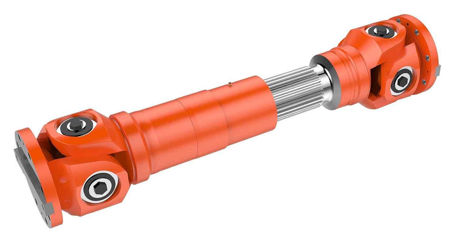
How do manufacturers ensure the compatibility of cardan shafts with different equipment?
Manufacturers take several measures to ensure the compatibility of cardan shafts with different equipment. These measures involve careful design, engineering, and manufacturing processes to meet the specific requirements of diverse applications. Let’s explore how manufacturers ensure compatibility:
1. Application Analysis:
– Manufacturers begin by analyzing the application requirements and specifications provided by customers. This analysis includes understanding factors such as torque, speed, misalignment, operating conditions, space limitations, and other specific needs. By evaluating these parameters, manufacturers can determine the appropriate design and configuration of the cardan shaft to ensure compatibility with the equipment.
2. Customization Options:
– Manufacturers offer customization options for cardan shafts to meet the unique requirements of different equipment. This includes providing various lengths, sizes, torque capacities, connection methods, and material options. Customers can work closely with manufacturers to select or design a cardan shaft that fits their specific equipment and ensures compatibility with the system’s power transmission needs.
3. Engineering Expertise:
– Manufacturers employ experienced engineers who specialize in cardan shaft design and engineering. These experts have in-depth knowledge of mechanical power transmission and understand the complexities involved in ensuring compatibility. They use their expertise to design cardan shafts that can handle the specific torque, speed, misalignment, and other parameters required by different equipment.
4. Computer-Aided Design (CAD) and Simulation:
– Manufacturers utilize advanced computer-aided design (CAD) software and simulation tools to model and simulate the behavior of cardan shafts in different equipment scenarios. These tools allow engineers to analyze the stress distribution, bearing performance, and other critical factors to ensure the shaft’s compatibility and performance. By simulating the cardan shaft’s behavior under various loading conditions, manufacturers can optimize its design and validate its compatibility.
5. Quality Control and Testing:
– Manufacturers have stringent quality control processes in place to ensure the reliability, durability, and compatibility of cardan shafts. They conduct thorough testing to verify the performance and functionality of the shafts in real-world conditions. This may involve testing for torque capacity, speed limits, vibration resistance, misalignment tolerance, and other relevant parameters. By subjecting the cardan shafts to rigorous testing, manufacturers can ensure their compatibility with different equipment and validate their ability to deliver reliable power transmission.
6. Adherence to Standards and Regulations:
– Manufacturers follow industry standards and regulations when designing and manufacturing cardan shafts. Compliance with these standards ensures that the shafts meet the necessary safety, performance, and compatibility requirements. Examples of such standards include ISO 9001 for quality management and ISO 14001 for environmental management. By adhering to these standards, manufacturers demonstrate their commitment to producing compatible and high-quality cardan shafts.
7. Collaboration with Customers:
– Manufacturers actively collaborate with customers to understand their equipment and system requirements. They engage in discussions, provide technical support, and offer guidance to ensure the compatibility of the cardan shafts. By fostering a collaborative relationship, manufacturers can address specific challenges and tailor the design and specifications of the shaft to meet the unique requirements of different equipment.
In summary, manufacturers ensure the compatibility of cardan shafts with different equipment through application analysis, customization options, engineering expertise, CAD and simulation tools, quality control and testing, adherence to standards, and collaboration with customers. These measures allow manufacturers to design and produce cardan shafts that meet the specific torque, speed, misalignment, and other requirements of various equipment, ensuring optimal compatibility and efficient power transmission.
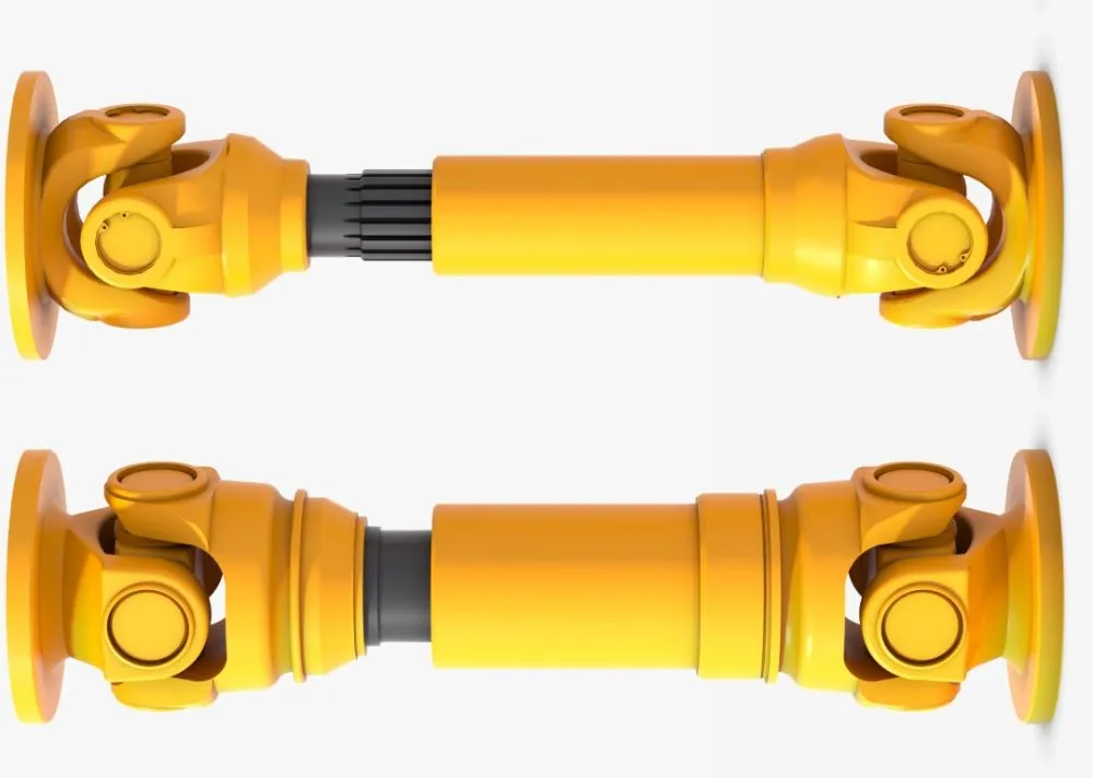
Are there any emerging trends in cardan shaft technology, such as lightweight materials?
Yes, there are several emerging trends in cardan shaft technology, including the use of lightweight materials and advancements in design and manufacturing techniques. These trends aim to improve the performance, efficiency, and durability of cardan shafts. Here are some of the notable developments:
1. Lightweight Materials:
– The automotive and manufacturing industries are increasingly exploring the use of lightweight materials in cardan shaft construction. Materials such as aluminum alloys and carbon fiber-reinforced composites offer significant weight reduction compared to traditional steel shafts. The use of lightweight materials helps reduce the overall weight of the vehicle or machinery, leading to improved fuel efficiency, increased payload capacity, and enhanced performance.
2. Advanced Composite Materials:
– Advanced composite materials, such as carbon fiber and fiberglass composites, are being utilized in cardan shafts to achieve a balance between strength, stiffness, and weight reduction. These materials offer high tensile strength, excellent fatigue resistance, and corrosion resistance. By incorporating advanced composites, cardan shafts can achieve reduced weight while maintaining the necessary structural integrity and durability.
3. Enhanced Design and Optimization:
– Advanced computer-aided design (CAD) and simulation techniques are being employed to optimize the design of cardan shafts. Finite element analysis (FEA) and computational fluid dynamics (CFD) simulations allow for better understanding of the structural behavior, stress distribution, and performance characteristics of the shafts. This enables engineers to design more efficient and lightweight cardan shafts that meet specific performance requirements.
4. Additive Manufacturing (3D Printing):
– Additive manufacturing, commonly known as 3D printing, is gaining traction in the production of cardan shafts. This technology allows for complex geometries and customized designs to be manufactured with reduced material waste. Additive manufacturing also enables the integration of lightweight lattice structures, which further enhances weight reduction without compromising strength. The flexibility of 3D printing enables the production of cardan shafts that are tailored to specific applications, optimizing performance and reducing costs.
5. Surface Coatings and Treatments:
– Surface coatings and treatments are being employed to improve the durability, corrosion resistance, and friction characteristics of cardan shafts. Advanced coatings such as ceramic coatings, diamond-like carbon (DLC) coatings, and nanocomposite coatings enhance the surface hardness, reduce friction, and protect against wear and corrosion. These treatments extend the lifespan of cardan shafts and contribute to the overall efficiency and reliability of the power transmission system.
6. Integrated Sensor Technology:
– The integration of sensor technology in cardan shafts is an emerging trend. Sensors can be embedded in the shafts to monitor parameters such as torque, vibration, and temperature. Real-time data from these sensors can be used for condition monitoring, predictive maintenance, and performance optimization. Integrated sensor technology allows for proactive maintenance, reducing downtime and improving the overall operational efficiency of vehicles and machinery.
These emerging trends in cardan shaft technology, including the use of lightweight materials, advanced composites, enhanced design and optimization, additive manufacturing, surface coatings, and integrated sensor technology, are driving advancements in the performance, efficiency, and reliability of cardan shafts. These developments aim to meet the evolving demands of various industries and contribute to more sustainable and high-performing power transmission systems.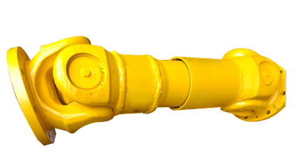
Can you explain the components and structure of a cardan shaft system?
A cardan shaft system, also known as a propeller shaft or drive shaft, consists of several components that work together to transmit torque and rotational power between non-aligned components. The structure of a cardan shaft system typically includes the following components:
1. Shaft Tubes:
– The shaft tubes are the main structural elements of a cardan shaft system. They are cylindrical tubes made of durable and high-strength materials such as steel or aluminum alloy. The shaft tubes provide the backbone of the system and are responsible for transmitting torque and rotational power. They are designed to withstand high loads and torsional forces without deformation or failure.
2. Universal Joints:
– Universal joints, also known as U-joints or Cardan joints, are crucial components of a cardan shaft system. They are used to connect and articulate the shaft tubes, allowing for angular misalignment between the driving and driven components. Universal joints consist of a cross-shaped yoke with needle bearings at each end. The yoke connects the shaft tubes, while the needle bearings enable the rotational motion and flexibility required for misalignment compensation. Universal joints allow the cardan shaft system to transmit torque even when the driving and driven components are not perfectly aligned.
3. Slip Yokes:
– Slip yokes are components used in cardan shaft systems that can accommodate axial misalignment. They are typically located at one or both ends of the shaft tubes and provide a sliding connection between the shaft and the driving or driven component. Slip yokes allow the shaft to adjust its length and compensate for changes in the distance between the components. This feature is particularly useful in applications where the distance between the driving and driven components can vary, such as vehicles with adjustable wheelbases or machinery with variable attachment points.
4. Flanges and Yokes:
– Flanges and yokes are used to connect the cardan shaft system to the driving and driven components. Flanges are typically bolted or welded to the ends of the shaft tubes and provide a secure connection point. They have a flange face with bolt holes that align with the corresponding flange on the driving or driven component. Yokes, on the other hand, are cross-shaped components that connect the universal joints to the flanges. They have holes or grooves that accommodate the needle bearings of the universal joints, allowing for rotational motion and torque transfer.
5. Balancing Weights:
– Balancing weights are used to balance the cardan shaft system and minimize vibrations. As the shaft rotates, imbalances in the mass distribution can lead to vibrations, noise, and reduced performance. Balancing weights are strategically placed along the shaft tubes to counterbalance these imbalances. They redistribute the mass, ensuring that the rotational components of the cardan shaft system are properly balanced. Proper balancing improves stability, reduces wear on bearings and other components, and enhances the overall performance and lifespan of the shaft system.
6. Safety Features:
– Some cardan shaft systems incorporate safety features to protect against mechanical failures. For example, protective guards or shielding may be installed to prevent contact with rotating components, reducing the risk of accidents or injuries. In applications where excessive forces or torques can occur, cardan shaft systems may include safety mechanisms such as shear pins or torque limiters. These features are designed to protect the shaft and other components from damage by shearing or disengaging in case of overload or excessive torque.
In summary, a cardan shaft system consists of shaft tubes, universal joints, slip yokes, flanges, and yokes, as well as balancing weights and safety features. These components work together to transmit torque and rotational power between non-aligned components, allowing for angular and axial misalignment compensation. The structure and components of a cardan shaft system are carefully designed to ensure efficient power transmission, flexibility, durability, and safety in various applications.


editor by CX 2023-11-20